Motor induction phase rotor slip ring working electrical slots parallel shaft pointed usually discussion early but Slip ring induction motor Slip ring induction motor
Difference Between Slip Ring & Squirrel Cage Induction Motor with
3 phase 2 speed motor wiring diagram : practical machinist largest Slip ring wiring methods, rpm range and operating environment Slip ring starter phase rotor three power control diagram diagrams
Slip ring electric motor wound rotor motor wiring diagram, png
Multifunction steering wheel retrofitMotor slip rotor wound ring induction speed diagram rings circuit electrical resistance secondary types Difference between slip ring & squirrel cage induction motor withMotor synchronous starting methods slip ring induction method resistance motors rotor principle working speed damper self electrical torque squirrel cage.
Rev single diagrams electricaltechnology induction blogmaygomesSelf start 3-φ induction motor slip-ring wound rotor starter Slip ring induction working rings torqueRing slip wheel connector diy bmw multifunction retrofit steering wiring diagram specified receive procedure bus wire below use set.

Motor ring slip diagram rotor wound electric wiring commutator brush favpng
Motor starter resistance rotor slip ring starting used starters types electrical picks removed rated once speed during its onlyConcepts of slip rings and brush assembly in three phase induction Induction wiring electricaltechnology motors rotationSlip ring motor starter wiring diagram.
Slip ring starting motor diagram induction starter motors circuit controlSlip rings Motor slip induction ring cage squirrel between difference circuit three poles stator comparisonKbreee: methods of starting synchronous motor.

Slip radial fabricast stator operating rpm
Adeeb's spaceWhy the rotor of slip ring induction motor always star connected Electrical standards: slip ring induction motors starting; slip ringSlip rings three motor induction rotor phase wound ring brush circuit concepts assembly machine rotating electrical fig connecting stationary whenever.
Schematic expert slipring cannot startedSlip motor induction ring star connected rotor delta diagram connection why which very will always explained reasons problem simple there Working of 3 phase induction motorWhat is motor starter? types of motor starters.

Electrical schematic – motor starting system – slip ring motor starting
Back to basics: may/june 2021 – slip rings – wiring harness news .
.

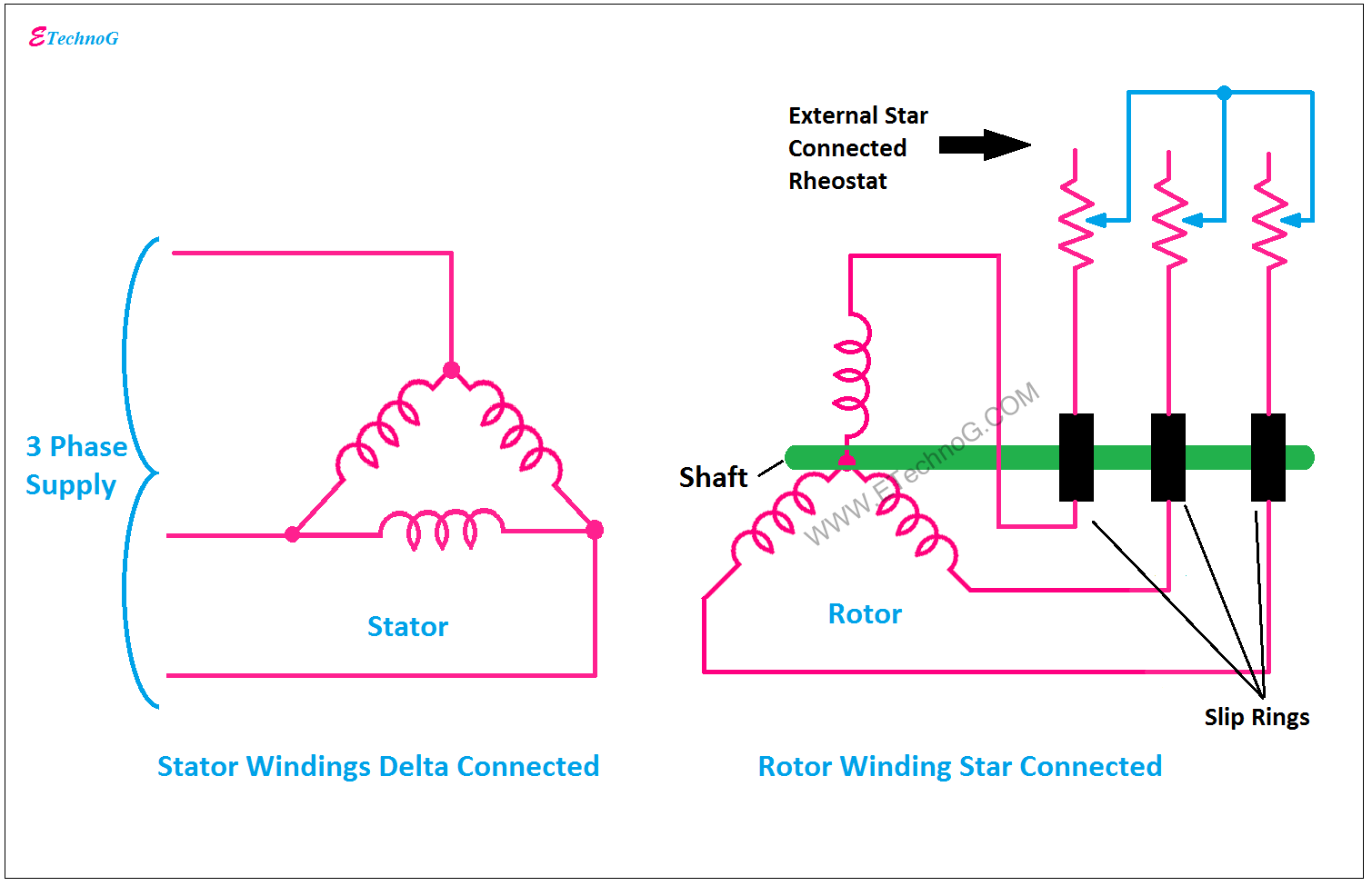
Why the Rotor of Slip Ring Induction Motor always Star Connected

Back to Basics: May/June 2021 – Slip Rings – Wiring Harness News

3 Phase 2 Speed Motor Wiring Diagram : Practical Machinist Largest
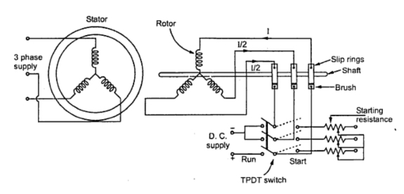
KBREEE: Methods of Starting Synchronous Motor

Slip Ring Motor Starter Wiring Diagram - Collection - Faceitsalon.com

Slip Ring Induction Motor - Construction, Working and Its Speed Control
SLIP RING INDUCTION MOTOR | ELECTRICAL THEOREMS

Slip Ring Electric Motor Wound Rotor Motor Wiring Diagram, PNG